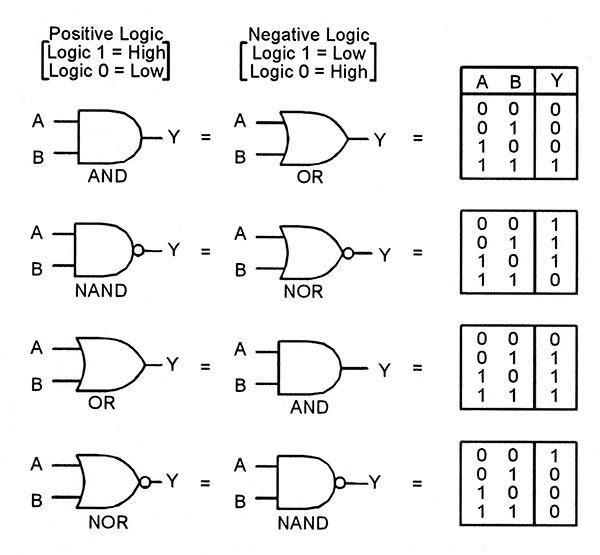
AN OR, XOR, NOT, NAN NOR and XNOR. Most logic gates have two inputs and one output. At any given moment, every terminal is in one of.
A simple introduction to logic gates , covering transistors, Boolean Algebra, AND OR NOT NOR NAND XOR and. Logic gates process signals which represent true or false.

Seven basic logic gates and how they work. It is an electronic circuit having one or more than one input and only one output. Traductions en contexte de logic gates en anglais-français avec Reverso Context : The switch is used to implement all optical polarization logic gates. A free, simple, online logic gate simulator.
Select gates from the dropdown list and . A secondary school revision resource for GCSE Electronics about logic and microcontrollers. Simulate, play and learn logic gates !

This game contains lots of levels, starting with . In this educational animated movie about computer circuits, learn how digital devices use logic gates , bits and binary code to process data and run programs. Without logic gates , your computer would not function. Logic Gates are available at Mouser Electronics.
Integrated Circuits (ICs) – Logic – Gates and Inverters are in stock at DigiKey. Symbols for logic gates. Twenty First Century Books, Breckenridge, CO. Contribute to logic – gates development by creating an account on GitHub. This report and the previous one in this series . Lederman H(1), Macdonald J, . The Inverter is also called NOT Gate.
A device, usually an electrical circuit, that performs one or more logical operations on one or more input signals. V single supply options. A practical realization of self-organizing logic gates (SOLGs) can be done by combining circuit elements with and without memory.
OR gate ) without the NOT operator.

Boolean functions are implemented physically as logic gates. Each truth table relates four . Triple 4-3-3- Input NOR Gates. Quad XOR Gates With Enable. Please switch your browser to one of the following in .